Evaluating Tolerance Limits Practically
How we defined achievable fit standards and moved past theoretical design models to optimize real-world parts assembly.
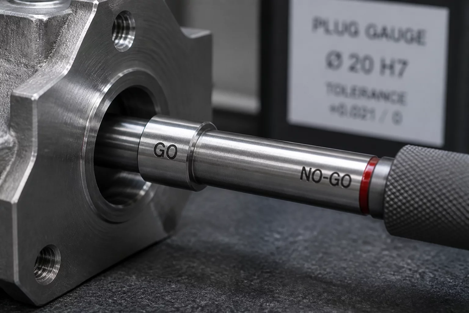
Achieving a perfect fit between 3D-printed parts requires looking beyond nominal CAD dimensions. When engineers design components, they often assume that a 10.0mm pin will slide smoothly into a 10.0mm hole. In reality, material shrinkage, nozzle extrusion width, and thermal expansion cause variations that prevent assembly. This case study details our systematic testing to establish practical tolerance limits for FDM printing, helping teams avoid costly redesigns and post-processing adjustments.
Overview & Objective
Our main objective was to determine the baseline deviation of our printing equipment under standard production runs. We observed that parts frequently required manual sanding or filing to fit together correctly. This manual intervention indicated that our nominal models lacked the necessary clearance offsets. To resolve this, we set out to establish a reliable design chart that engineers can consult before sending files to the production floor. The goal was to find a balance where parts fit securely without being too loose or requiring secondary modifications.
Designing for zero tolerance is a recipe for assembly failure. True engineering success lies in identifying the exact range of functional variation and planning for it.
— Marcus Wright, Technical Lead
Implementation & Methodology
To determine the actual deviations, we designed a custom test coupon featuring a series of pins and slots with clearances ranging from 0.05mm to 0.35mm. We printed these coupons using standard PLA and PETG filaments across three different machines. After printing, we used calibrated go/no-go plug gauges to verify the inner diameters. We also recorded the ambient temperature during each run. This structured approach allowed us to map the correlation between the nominal CAD files and the final physical measurements across different materials.
Key Takeaways & Lessons
The test runs yielded clear thresholds for assembly design. A clearance of 0.15mm provides a reliable sliding fit for moving assemblies, while a 0.10mm clearance creates a firm press-fit. Clearances below 0.08mm consistently fail due to normal layer inconsistencies and minor over-extrusion. We also noted that PETG exhibits slightly more shrinkage than PLA, requiring an additional 0.02mm of clearance. Incorporating these values directly into the CAD models eliminates the need for manual post-processing and ensures high repeatability.
Discussion & Input
Add Your Analysis